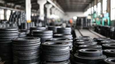
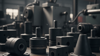
Choosing the right Rubber Isolation Mounts is not a simple catalog exercise. It is a practical decision involving load, movement, temperature, frequency, and installation space. A mount supporting a compact pump may fail when exposed to continuous misalignment, oil mist, or repeated shock. The correct choice must fit the real machine, not an ideal specification sheet.
Rubber scientist Dr. Alan N. Gent observed, “The properties of rubber are strongly dependent on time and temperature.” That principle remains important today. A mount may feel firm during a workshop test, then soften after months of heat and compression. It may also transmit unwanted vibration when its stiffness matches the machine’s operating frequency. Small details matter.
Start with the actual load at each mounting point. Check whether the force is vertical, lateral, or combined. Then review the rubber compound, hardness, deflection, damping, and environmental resistance. Neoprene, EPDM, silicone, and natural rubber behave differently. The wrong compound can crack, swell, or lose resilience. It happens.
This guide explains how to compare Rubber Isolation Mounts with greater confidence. It considers equipment weight, vibration frequency, shock loads, temperature range, chemical exposure, and service life. Installation quality also deserves attention. Uneven tightening can distort the mount and create unexpected vibration paths. A better process includes measurement, prototype testing, and periodic inspection. Still, no selection method is perfect. Field conditions often expose assumptions that laboratory data misses. That uncertainty should encourage careful testing, not careless guessing.
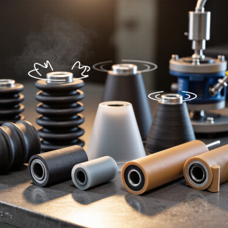
Rubber isolation mounts are flexible components placed between equipment and its supporting structure. They reduce vibration by absorbing movement instead of transferring it directly into the frame. Most mounts use an elastomer that compresses, stretches, or moves in shear. Each motion changes the mount’s stiffness and damping behavior.
The correct mount depends on load, vibration frequency, temperature, and installation direction. A mount that is too stiff may transmit humming through the floor. One that is too soft may allow excessive movement during startup. In field inspections, uneven loading often causes premature cracking. That detail is easy to miss. Check the actual load on each mount, not only the machine’s total weight.
Tips: Measure operating vibration before selecting a mount. Confirm the expected load range and safety margin. Check oil exposure, heat, moisture, and ultraviolet conditions. Keep the mounting surfaces level and tighten fasteners evenly. Over-tightening can restrict rubber movement and reduce isolation. After installation, inspect the mount during operation. Look for bulging, slipping, unusual noise, or metal contact. Testing matters. A calculated solution can still perform poorly when the real operating frequency differs from the design estimate. Allow room for adjustment when conditions are uncertain.
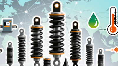
Choosing rubber isolation mounts starts with understanding the equipment, not the mount catalog. Record the machine’s total operating weight, footprint, center of gravity, and mounting points. Include fluids, tools, guards, and materials added during operation. Static weight alone can mislead you.
Measure the vibration direction carefully. The machine may move vertically, horizontally, or in several directions at once. Note the operating speed, starting torque, stopping impact, and nearby sensitive equipment. A compressor and a precision measuring table need very different isolation behavior. Calculate the load on each mount, then account for uneven distribution. The heaviest point may not sit near the center.
Environmental conditions matter just as much. Check temperature, moisture, oils, cleaning chemicals, and outdoor exposure. Confirm the available height and diameter before selecting a mount. Inspect bolt sizes, thread direction, clearance, and the required compression or shear movement. A mount that fits the drawing may fail during installation.
Leave room for real-world uncertainty. Field measurements are often incomplete, and operating loads can change. I have seen installations fail because operators ignored a temporary production load. A practical safety factor helps, but excessive stiffness can transmit vibration instead of reducing it. Test the equipment at normal speed and during startup when possible. Record noise, movement, and fastener behavior. The first calculation is rarely perfect. Recheck it.
Material selection starts with the operating environment. Natural rubber offers strong resilience and fatigue resistance for many low-temperature applications. Nitrile rubber suits oil exposure better, while silicone maintains flexibility across wider temperature changes. A 2023 review in Polymer Testing reported that filler content and crosslink density can substantially change rubber stiffness and damping. Therefore, do not select material by temperature alone. Check oil, ozone, humidity, and chemical contact.
Shape controls how the mount carries force. A cylindrical bush usually works well in shear. A conical mount can manage compression while limiting movement. A bonded mount may reduce installation space, but it can transfer more force when overloaded. ISO 10846-1 recommends measuring transfer stiffness under defined frequency and load conditions. That matters because a mount rated at 10 Hz may behave differently at 100 Hz. Small details matter.
Hardness is only a starting point. Shore A values do not directly equal dynamic stiffness. ASTM D395 Method B commonly evaluates compression set after 22 hours at 70°C. This test helps compare permanent deformation, but it does not represent every field condition. Select hardness from the actual load-deflection curve, not a catalog number. A practical target often keeps static deflection around 1–3 millimeters, depending on the vibration system. I would still challenge that range during testing. Temperature, preload, and aging can change it. Build prototypes, measure transmissibility, and review the data honestly.
Start with the real operating load, not only the equipment’s nameplate weight. Divide the total mass by the number of mounts, then allow for uneven distribution. A four-mount machine weighing 800 kilograms may place 240 kilograms on one mount and 187 kilograms on another. Select each mount above its highest working load. A practical safety margin of 1.5 to 2 times can cover starting forces, transported equipment, and minor installation errors.
Deflection is closely linked to stiffness. Use the basic relationship
where k is stiffness, F is load, and δ is deflection. If one mount carries 2,400 newtons and compresses 6 millimeters, its stiffness is about 400 N/mm. Too little deflection may transmit vibration. Too much may cause movement, alignment problems, or bottoming out. Measure the loaded height after installation, because catalog values rarely match every real condition.
Vibration selection needs more than a rubber hardness label. Estimate the system’s natural frequency with
Effective isolation usually requires the disturbing frequency to exceed the natural frequency by about 1.4 times or more. Damping also matters during startup and shutdown. I have seen neat calculations fail when motor imbalance, piping forces, or a flexible frame were ignored. Check vibration at the machine and supporting structure. Leave room for aging, temperature changes, and compression set. The “perfect” mount on paper may still need adjustment in the field.
Correct installation begins with the load, not the catalog photograph. Check static weight, movement direction, temperature, and nearby fluids. A mount that looks oversized may still sag under uneven loading. Smithers’ 2024 rubber industry outlook estimates global rubber consumption at more than 30 million tonnes annually. This scale reflects rubber’s wide use, but compound selection remains application-specific.
During installation, keep mounting surfaces clean and parallel. Tighten fasteners gradually, using the specified torque. Do not pull a misaligned mount into position with bolts. That shortcut can create constant shear stress.
Look for cracks around the bolt sleeve, permanent flattening, surface swelling, and shiny contact marks. Measure height against the original installation record. A height loss of roughly 10% deserves engineering review, especially under rotating equipment. Compare vibration readings with the baseline. ISO 20816 provides guidance for evaluating machine vibration, but it does not replace site-specific limits.
Replace a mount when rubber separates from metal, cracking reaches the sleeve, or movement becomes uncontrolled. Replace the complete matched set when load sharing depends on identical stiffness. One new mount beside aged mounts can create uneven loading.